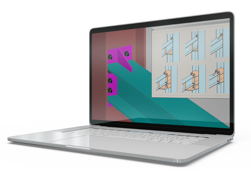
TecnoMETAL

BIM Solution for steel structures and connections verification for AutoCAD or BricsCAD.
You can create a 3D model of the structure and verify the connections. Inside the software there are more than 1000 customizable connections and automatic intelligence procedures to quickly create the most common steel structures (towers, stairs, purlins, bracings, truss ...)
TecnoMETAL Premium contains all the functions of TecnoMETAL Standard, in addition to the functions below

TecnoMETAL allows you to quickly design steel frame structures with all necessary workings. The 3d models allow to automatically extract the two-dimensional drawings, the workshop scketches and the cutting lists of the materials for production.
TecnoMETAL A.I. are tools that greatly facilitate the modeling work and allow you to include automatically elements, such as: wireframes, connections, braces, security stair, sailor type stairs, spiral stairs, handrails, towers, purlins, bridges, curtain walls, porches, steps, circular platforms, piping supports, tie rods, turnbuckles, hoppers, rectangular and polygonal pylons, etc.
TecnoMETAL allows you to create a structure according to BIM logic, so you can share the models with other 3D software such as Revit, Inventor, Solidworks, PTC CREO Modeling, Esain, Smartplan, Cadworks, Naviswork. You can create IFC, STP, PML, SDNF, DWF 3D files.
TecnoMETAL allows to perform workings on the inserted elements, profiles or plates. The workings can be inserted automatically, recognizing the robot workings or manual workings at the designer's discretion. In addition to standard machining workings, welding preparations can be inserted which will be highlighted in the CAM file to facilitate the production process.
TecnoMETAL also contains a number of extremely useful commands such as sheet metal nesting, DXF file creation from CAM files, and vice versa, creating bent profile CAM files and dividing welded profiles into plates, searching for and checking identical cam files, creating families for Revit, export list of necessary treatments (with division between cuts, holes ...), increase or decrease of holes diameter directly in the CAM file.
TecnoMETAL contains a series of safety commands that are important in the modelling phase. These commands can automatically delete the errors, recreate groups, and automatically delete elements that are no longer needed and that cause problems by making the project bigger than necessary. There are also commands that verify the marks and positions and notify in case of inconsistencies (essential when revising the project). It is also possible to verify the connections through the insert connection macro. The interferences can be checked by means of a specific command, and overlapping plates and bolts can be eliminated automatically.
From the 3D Model are automatically obtained the sketches for the production and the assembly views. It is also possible to obtain a table of connections designed with the 3d Connections macro. Extraction settings can be customized. It is possible to insert 2D perspective drawings including mark, position, and bolt information. Detail drawings can be generated in two ways: Single Drawing = one piece per drawing and Multi Drawing = in which the designer selects and inserts single elements.
The Sketches are a CAM-NC files and contain all the information for the fabrication and also for CNC machines. The sketches can be displayed on the computer and it is possible to set up the display. The CAM file can be exported as DXF, PDF, DWG, NC and DSTV file. It is possible to create a CAM file from a bent profile as a plate development, welded or composite, it is possible to create a CAM file from a tube with cuts and you can also import the CAM file to scale as a file DWG.
Compare TecnoMETAL solutions to choose the
one that best suits your needs
39045-8778577